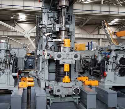
Vertical stand

| Location | Components |
| Rolling mill | A. Motor coupling B. Coupling guard C. Motor baseplate D-E. Gearbox / pinion stand F. Vertical spindles G. Coupling boxes (stand side) H. Coupling boxes (gearbox side) I. Spindle guard J. Coupling holder for in-line changing K. Baseplate for in-line changing L. Gearbox baseplate M. cartridge extraction device |
| Dute | |
Rolling in vertical position.
| |
| |
A-Motor coupling Motor torque is transmitted to the pinion stand via a gear type coupling. To protect the drive elements the coupling is provided with a torque-limiting device by means of shear pins. In case of overload the shear pins will break. The pins can be easily replaced | |
B- Coupling guard Installed around the coupling for operator safety. made of welded steel.
| |
C- Motor baseplate Fabricated steel structure. | |
D.E- Gearbox / pinion stand Provided with helical gear teeth dimensioned according to ANSI-AGMA Standards. Transmission gears in NiCrMo steel (casehardened by carburising) mounted on roller bearings
| |
F- Horizontal spindles The rolling torque is transmitted by universal, telescopic type spindles connected to the rolls and to the pinion shafts through the coupling boxes. | |
G- Coupling boxes (stand side) Coupling boxes transmit the torque from the spindles to the rolling rolls via the flat roll ends. Automatic alignment of flat roll ends. H- Coupling boxes (gearbox side) Coupling boxes transmit the torque from the pinion stand to the spindles via hub. | |
I- Spindle guard welded steel construction.
| |
J- Coupling holder for in-line changing To support the spindles during stand changing operations. The spindle couplings on the stand side are supported by self-centring chocks fitted with ball bearings; the chocks are enclosed in a horizontally movable frame. The coupling chocks automatically cover the whole centre distance range of the stands. The coupling holder moves with the stand during rolling/groove changing operations and is hydraulically disengaged for stand changing operations. | |
K- Base plate for in-line changing A concrete frame is provided to support the reduction gearbox with the motor coupling and electric motor. Installed on the same concrete frame is a welded steel baseplate with machined sliding surfaces for vertical shifting of the roll unit together with the coupling holder. Mechanical clamps are included to lock the stand container onto the baseplate Groove adjustment Groove adjustment is performed by means of a two hydraulically driven screw jacks.
| |
L- Gearbox baseplate Gearbox baseplate in welded steel structure. Fixed to the foundations.
| |
M- Cartridge extraction device Stand cartridge extraction / insertion is performed by a car driven by hydraulic cykibder. | |

